- Gotronik PPHU
NIP: PL8971671385 - E-mail:biuro@gotronik.pl
- TelefonBiuro: 71 351 10 31
Zamówienia: 511-048-814
Pyt, techniczne: 514-349-414 - Gadu Gadu1767965
5476656
8342724
- 1
Papier termotransferowy A4 do płytek drukowanych
- 2
Filtr 16,8mm do ZD915 ZD917 ZD-915 ZD-917
- 3
Przetwornica napięcia 12V Step Up
- 4
Moduł szufladki magazynowej z przegródkami 180x110x55mm
- 5
Listwa kołkowa 1x40pin precyzyjna raster 2,54mm czarna
- 6
Krokodylek 2mm do przewodów miernika CZERWONY
- 7
Krokodylek 2mm do przewodów miernika CZARNY
- 8
Chwytak pomiarowy pazurkowy czerwony
- 9
Chwytak pomiarowy pazurkowy czarny
- 10
Topnik flux AMTECH RMA-223-UV opakowanie 10g

UT15C wskaźnik napięcia 12-690V AC/DC114,00 zł brutto92,68 zł netto

Kamera termowizyjna UTi260B rozdzielczość 256 x 1921 299,00 zł brutto1 056,10 zł netto

UPO1202CS oscyloskop cyfrowy 2x200MHz1 950,00 zł brutto1 585,37 zł netto
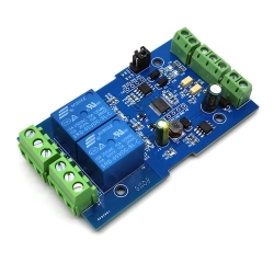
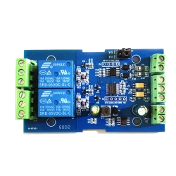
Moduł 2 przekaźników sterowanych RS485 Modbus RTU

Czas wysyłki: 24 godziny
Koszt wysyłki: od 11,99 zł
Numer katalogowy: BTE-951
Stan magazynowy: ![]()
Stan produktu: Nowy
- Opis produktu
- Recenzje produktu (1)
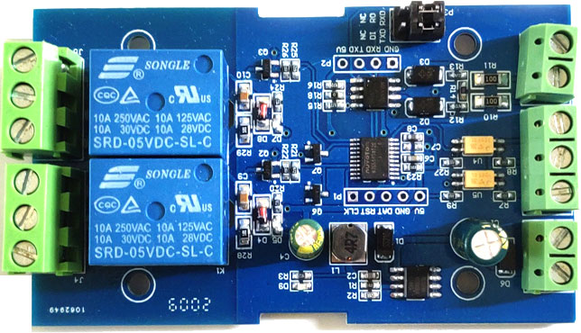
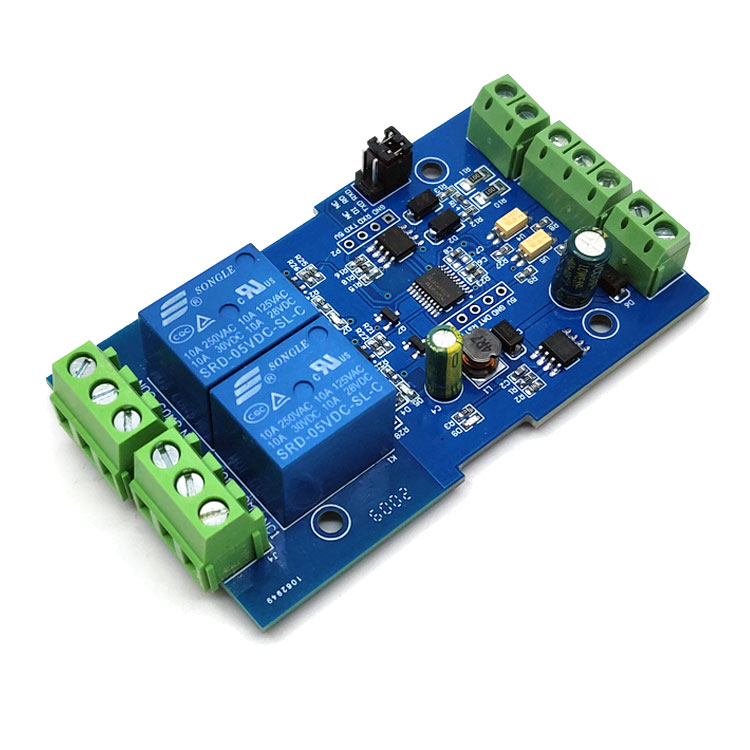
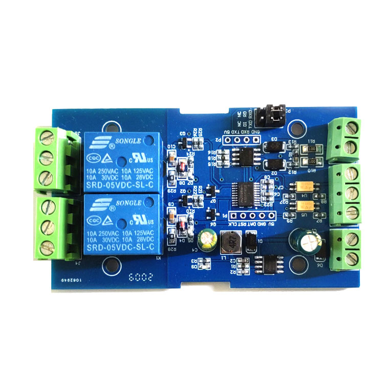
- 8 bitowy mikroprocesor MCU
- układ MAX485
- liczba przekaźników: 2
- protokół komunikacyjny: Modbus RTU
- interfejs komunikacyjny: UART RS485 / TTL
- szybkość transmisji: 4800/9600/19200 (domyślnie: 9600)
- obsługa trybu oszczędzania energii
- napięcia wejściowe: 3,3V do 30V dc
- na wejściu transoptor
- wejście zasilania nie może służyć do zasilania przekaźnika
- regulacja opóźnienia
- maksymalna wartość opóźnienia: 6553,5 -> 0xFFFF x 0,1s
- adres urządzenia: 1 -255 (domyślnie 255)
- utrzymywanie adresu po odłączeniu zasilania
- przekaźnik 5V
- złącza terminal block oraz miejsca do dolutowania przewodów lub gniazdo goldpin
- maksymalne obciążenie styków przekaźnika: 10A/250VAC lub 10A/30VDC
- żywotność przekaźnika: około 100000 cykli
- dioda LED informująca o załączeniu przekaźnika
- napięcia zasilania: 7 – 24V DC
- zabezpieczenie przed podłączeniem odwrotnej polaryzacji
- możliwość komunikacji przez UART
- wymiary: 63 x 36 x 20 mm
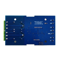
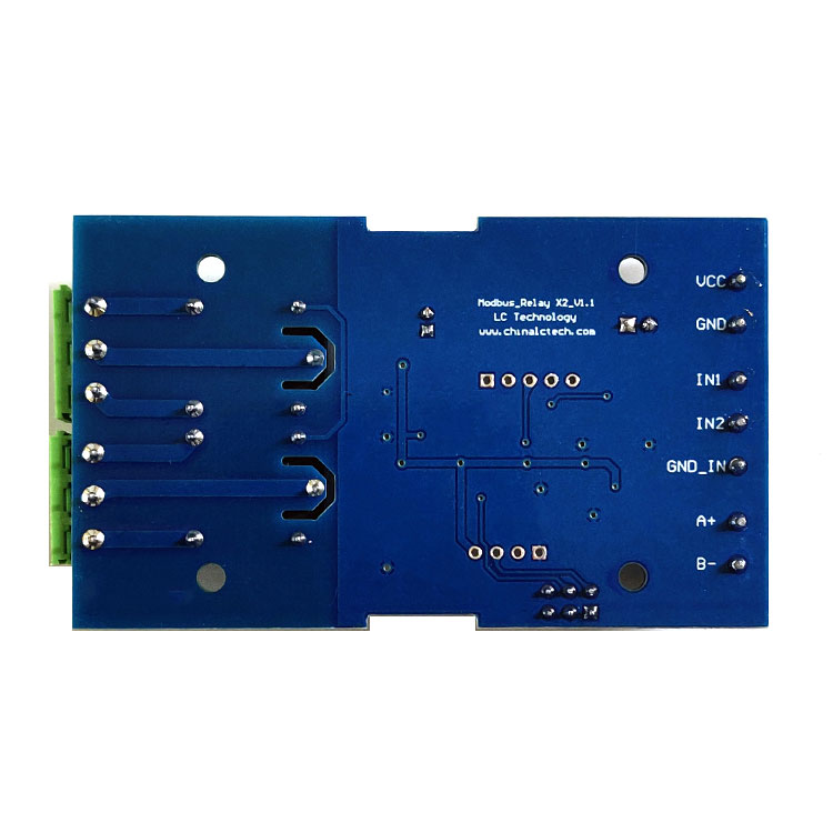
opis wyprowadzeń:
- Vcc – zasilanie +
- GND – masa -
- IN – wejście sygnału na transoptor
- A +, B-: interfejs komunikacyjny RS485
- NC - normalnie zamknięty
- NO – normalnie otwarty


1.Onboard mature and stable 8-bit MCU and RS485 level communication chip.
2.Communication protocol:support standard Modbus RTU protocol
3.Communication Interface:support RS485/TTL UART interface
4.Communication baud rate: 4800/9600/19200,default 9600bps, Support power-down save.
5.Optocoupler input signal range, DC3.3-30V(this input can’t use relay control)
6.Output signal:relay switch signal, support manual control,flash OFF/ON mode,The delay base is 0.1S,the maximum allowable flash OFF/ON time is 0xFFFF*0.1S=65535*0.1S=6553.5S
7.Device address:range:1-255,default 255,Support power-down save
8.Baud rate/optocoupler input status/relay status/device address can be read by software/commands.
9.On-board 2 way 5V,10A/250V AC 10A/30V DC relay,can continuously sucking 100,000 times, it has diode flow protection for short response times.
10. On-board relay switch indicator.
11.Supply voltage:DC7-24V,with input anti-reverse protection
3, Introduced the hardware and instructions
1.board size:
2.interface description.
1,VCC,GND:DC7-24V power input
2, DC3.3-30V Optocoupler signal input:
IN1:channel 1 positive
IN2:channel 2 positive
GND_IN:common terminal negative
3, A+,B-:RS485 communication Interface
4,relay 1 switch signal output:
NC1:Normally closed end
COM 1: Common end
NO1:normally opened end
5,Relay 2 switch signal output:
NC2:Normally closed end
COM 2: Common end
NO2:Normally opened end
6, Relay indicator:Lights up when the relay ON.
7,GND,RXD,TXD:TTL level UART communication Interface,GND,RXD,TXD separately connect to the external control terminal GND,TXD,RXD; support connect 3.3V/5v external TTL serial ports .
8. RS485 and TTL serial ports select , when use RS485 communicating, DI connect to TXD 、RO connect to RXD: DI and RO connect NC terminal when use TTL communicating.
3,Modbus RTU introduction of instruction
Modbus device through receive from external control terminal (like Host computer/MCU ) Modbus RTU instruction to perform related operations, one frame instruction generally consists of device address, function code, register address, register data, and check code,frame length is related to function code. Each frame date’s first byte is the device address.can set range on 1-255 default 255(scilicet 0xFF),the last 2byte is CRC check code.
Suppose the device address is 255, the commonly used Modbus RTU instructions are as follows:
(2)1, Open no.1 relay (manual mode)
send :FF 05 00 00 FF 00 99 E4
return :FF 05 00 00 FF 00 99 E4
remarks: (1)the 3--4th byte of the transmitted frame represents the relay address,the relay 1-relay 8 address are respectively 0x0000,0x0001,0x0002,0x0003,0x0004,0x0005,0x0006,0x0007
(2)the 5--6th byte of the transmitted frame represents Data,0xFF00 represent turn on relay,0x0000 represents turn off relay
2, Turn off the relay No. 1 (manual mode)
send : FF 05 00 00 00 00 D8 14
return : FF 05 00 00 00 00 D8 14
3, Turn on the relay No. 2 (manual mode)
send : FF 05 00 01 FF 00 C8 24
Return : FF 05 00 01 FF 00 C8 24
4, Turn off the relay no.2 (manual mode )
send : FF 05 00 01 00 00 89 D4
return : FF 05 00 01 00 00 89 D4
5, Turn on all relay
send :FF 0F 00 00 00 08 01 FF 30 1D
return :FF 0F 00 00 00 08 41 D3
6, Turn off all relay
send :FF 0F 00 00 00 08 01 00 70 5D
return :FF 0F 00 00 00 08 41 D3
7,Set the device address to 1
send :00 10 00 00 00 01 02 00 01 6A 00
return :00 10 00 00 00 01 02 00 01 6A 00
remark:The 9th byte of the transmitted frame, 0x01 is the written device address.
8, Set the device address to 255
send :00 10 00 00 00 01 02 00 FF EB 80
return :00 10 00 00 00 01 02 00 FF EB 80
remark:The 9th byte of the transmitted frame, 0xFF is the written device address.
9,Read device address
send:00 03 00 00 00 01 85 DB
return :00 03 02 00 FF C5 C4
remarks:The 5th byte of the Return frame, 0xFF is the read device address
10, read relay state
send :FF 01 00 00 00 08 28 12
return :FF 01 01 01 A1 A0
remarks:The 4th byte of the Return frame,Bit0--Bit7 of 0x01 representing relay 1-relay 8, 0 is turn off .1 is turn on.
11, Read optocoupler input status
send : FF 02 00 00 00 08 6C 12
return : FF 02 01 01 51 A0
remarks:The 4th byte of the Return frame, Bit0--Bit7 of 0x01 represent optocoupler1- optocoupler 8 input signal ,0 represent low level ,1 represent high level
12, Set the baud rate to 4800
send : FF 10 03 E9 00 01 02 00 02 4A 0C
return :FF 10 03 E9 00 01 C5 A7
remarks: the 9th byte of the transmitted frame is the baud rate setting value ,0x02, 0x03, x04 represents 4800, 9600, 19200
13, Set the baud rate to 9600
send : FF 10 03 E9 00 01 02 00 03 8B CC
return : FF 10 03 E9 00 01 C5 A7
14,Set the baud rate to 9600
send :FF 10 03 E9 00 01 02 00 04 CA 0E
return : FF 10 03 E9 00 01 C5 A7
15,Read the baud rate
send : FF 03 03 E8 00 01 11 A4
return : FF 03 02 00 04 90 53
remarks :The 5th byte of the Return frame represent baud rate, 0x02, 0x03, x04 represents 4800,9600,19200.
(2)16,Turn on no.1 relay (flash ON mode )
send :FF 10 00 03 00 02 04 00 04 00 14 C5 9F
return :FF 10 00 03 00 02 A4 16
remarks:(1)the 3-4th byte of the transmitted frame is represent relay address,relay1-relay8’s address separately is 0x0003,0x0008,0x000D,0x0012,0x0017,0x001C,0x0021,0x0026
(2)The 10th-11th byte of the transmitted frame represents the delay setting value, and the delay base is 0.1S, so the delay time is 0x0014*0.1=20*0.1S=2S, and the relay automatically turns off after turned on 2S
(2)17. Turn off no.1 relay(flash OFF mode)
send : FF 10 00 03 00 02 04 00 02 00 1E A5 99
return : FF 10 00 03 00 02 A4 16
remarks:(1)the 3-4th byte of the transmitted frame is represent relay address,relay1-relay8’s address separately is 0x0003,0x0008,0x000D,0x0012,0x0017,0x001C,0x0021,0x0026.
(2)The 10th-11th byte of the transmitted frame represents the delay setting value, and the delay base is 0.1S, so the delay time is 0x001E*0.1=30*0.1S=3S,and the relay automatically turns off after turned on 3S
4,Simple instructions
Modbus relay module can via RS485/TTL UART interface received from host computer /MCU’s Modbus RTU command to perform related operations.The following is an example of using the host computer software via the RS485 interface to open relay 1 (manual mode),suppose device address for 255.baud rate is 9600,Then steps of usage as follows:
1, VCC,GND: Connect to the power
2, A+,B- : Connect to A+ and B- of external device
3,turn on host computer software ModbusRTU configuration Tool,choose correct port number, baud rate is 9600.default address is 255,click open serial ports4,
then click ”JD1 ON” button can turn on relay 1 ,meanwhile indicator of relay 1 lights up
as below:
5,How to generate check code
Modbus RTU command are send through upper PC software (like:ModbusRTU configuration Tool ),CRC check code is auto generated, if want use serial debugging software (like SSCOM )to test Modbus relay module then need manually generated
CRC check code put on the end of transmitted frame, such as turn on the first relay (manual mode)
1.Turn on/off of relay (manual mode) transmitted frame composition :
device address (1Byte)+function code(1Byte)+ register address(2Byte) +register data (2Byte)+CRC check code (2Byte)
2, Suppose the device address is 0xFF, Then the first 6 bytes of the transmitted frame are FF 05 00 00 FF 00
3.Use the CRC check tool to check the 6 bytes
http://www.ip33.com/crc.html
4,Exchange checksum calculation result E499 high and low byte position then get CRC check code 99E4,and complete transmission frame:FF 05 00 00 FF 00 99 E4
5,Through serial port debugging software SSCOM V5.13.1 use the transmission frame send to modbus relay module can open first way relay (manual mode),as bellow:
Please refer our data if you need more detailed instructions and usage of way in host computer control modbus relay
 Data napisania recenzji: 27-09-2025
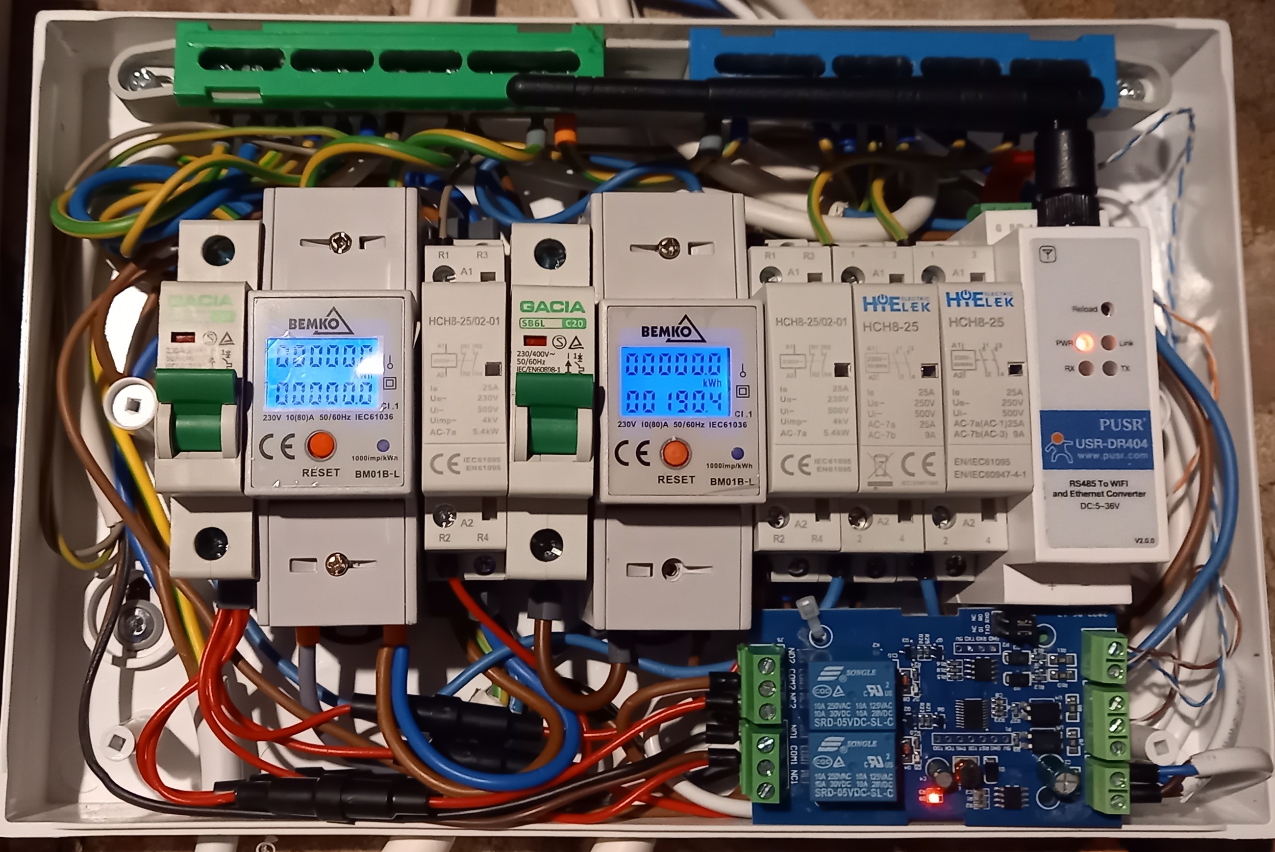
Bardzo fajna płytka , steruję (przez Home Assistant) zaworem i pompką centralnego ogrzewania . Tego właśnie potrzebowałem proste włącz wyłącz . Polecam.
Dokładamy wszelkich starań, by opinie pochodziły od klientów, którzy używali produktu lub go nabyli. Opinie są zbierane, weryfikowane i publikowane zgodnie z zasadami opisanymi w regulaminie sklepu.
Tylko zarejestrowani klienci mogą pisać recenzje do produktów. Jeżeli posiadasz konto w naszym sklepie zaloguj się na nie, jeżeli nie załóż bezpłatne konto i napisz recenzję.

